LED Panel 3 – Color Tricks with LED Panels

In the previous episode, we have shown how to clock out 128 bits of R/G/B data to each row of our 128×128 LED panel. Since only 1 out of 16 rows in each scan set (i.e. half of each LED panel) is selected for display each time, the software needs to walk through all the rows repeatedly to show a complete picture on the LED panel.
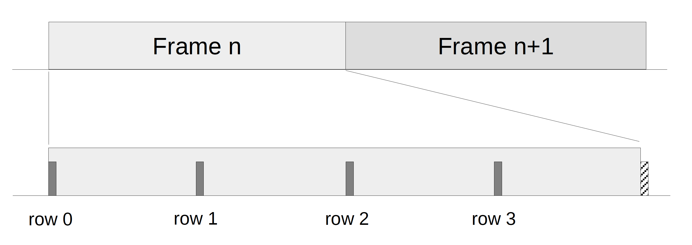
A loop in which all rows of a scan set are cycled through is called a frame, which is depicted in the diagram above. For simplicity each scan set in the example only contains 4 rows. Note that R/G/B data are clocked in ahead of time and only latched to the column output when the next row is selected.
At this point, all the LEDs on the panel can be turned on or off. By controlling the on/off state of the red, blue and green LEDs at each pixel location, we can create 8 (23) different colors. In other words, we have a color depth of 3 bits (i.e. 1 bit per primary color), which is not particularly impressive. A common method to show more colors is pulse-width-modulation (PWM). With PWM, a primary color LED is turned on for a portion of each frame (called duty cycle) that is proportional to its intensity making up a certain color.
Let’s start with an example of using PWM for a single LED, as illustrated in the diagram below. For simplicity we use a 3-bit value to encode its intensity, with 0 representing total darkness and 7 representing full brightness. To show an intensity of 0, the LED will be turned on for 0% of the frame duration, whereas for an intensity of 7, the LED will be turned on for 100% of the duration. Conceptually we can divide each frame into 7 slots, labelled as slot 0 to slot 6. The number of slots in which the LED is turned on is then equal to the intensity value from 0 to 7. In the diagram below, a red slot represents an “on” LED. The upper example shows an intensity of 1 while the lower one shows an intensity of 5.
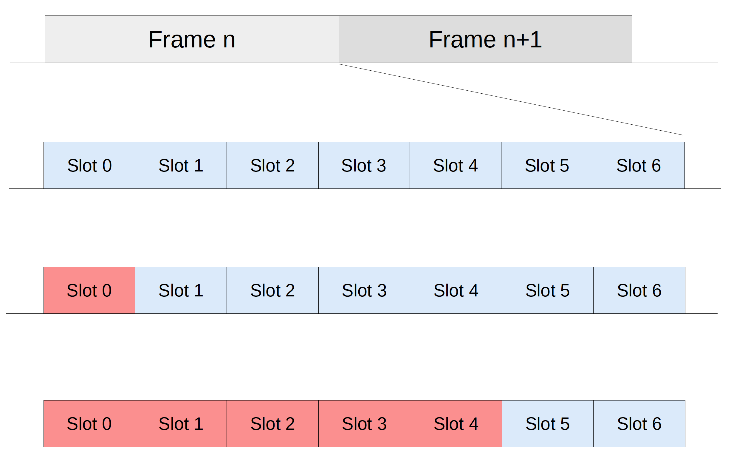
The resolution of the intensity depends on the number of bits used to encode the intensity. A larger number of bits (N) results in a higher resolution and more slots per frame (2N – 1). In the example above, each primary color (R/G/B) uses a 3-bit encoding, and altogether yields a 9-bit color depth with a resolution of 512 (29) colors.
For a single LED connected to a dedicated GPIO pin, we’d typically use a hardware timer of a microcontroller (called peripheral) to generate the PWM signal. Once set up, the hardware automatically toggles the GPIO pin to generate a clock signal with the specified frequency and duty cycle, with no software intervention. Unfortunately, this simple method does not apply here, since the LEDs on an LED matrix are not connected to dedicated GPIO pins but are multiplexed through shift registers and row selection.
To drive a PWM signal to an LED matrix, we need to take to a brute-force approach to manually refresh the entire display multiple times in each frame. Basically we divide a frame into (2N – 1) slots, where N is the number of bits per color (e.g. 3). In each slot, we set the on/off state of each R/G/B LED such that the number of “on” slots for each LED is equal to its desired intensity. However this approach is I/O expensive, since for each slot the microcontroller needs to clock out the color data for the entire display, especially for a high color depth. For instance, in order to achieve 24-bit real-color, each primary color will need an 8-bit resolution, which is equal to 256 slots. Refreshing the entire display 256 times per frame can be challenging even for a fast microcontroller. For example at a frame rate of 100Hz on an 1:16 LED panel (i.e. 16 rows per scan set), each slot lasts 1 / (100 * 256 * 16) = 2.4us.
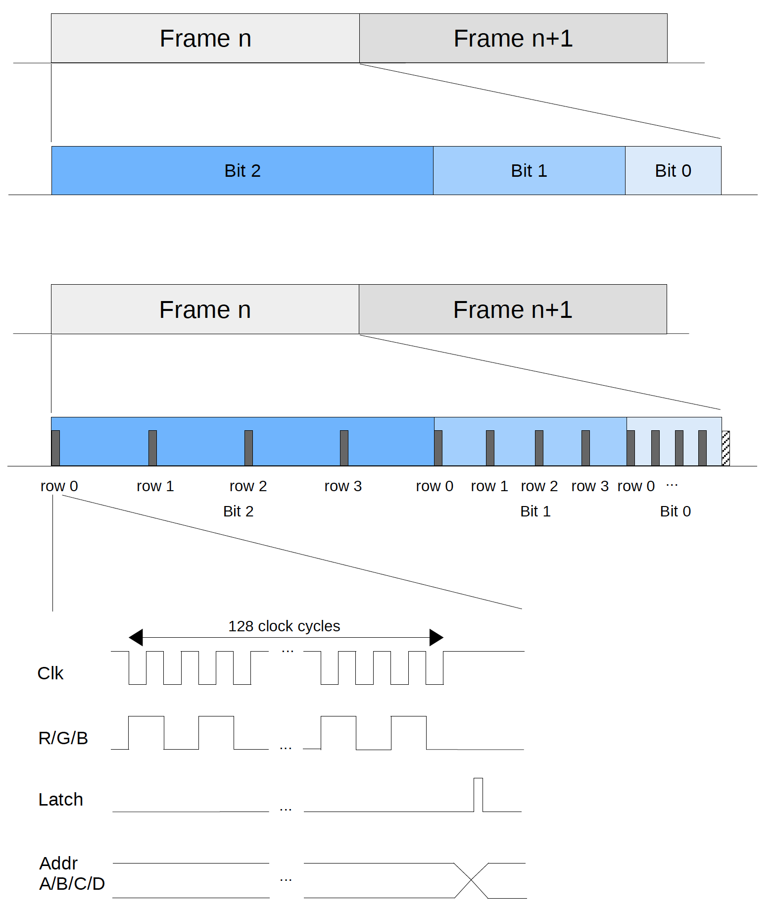
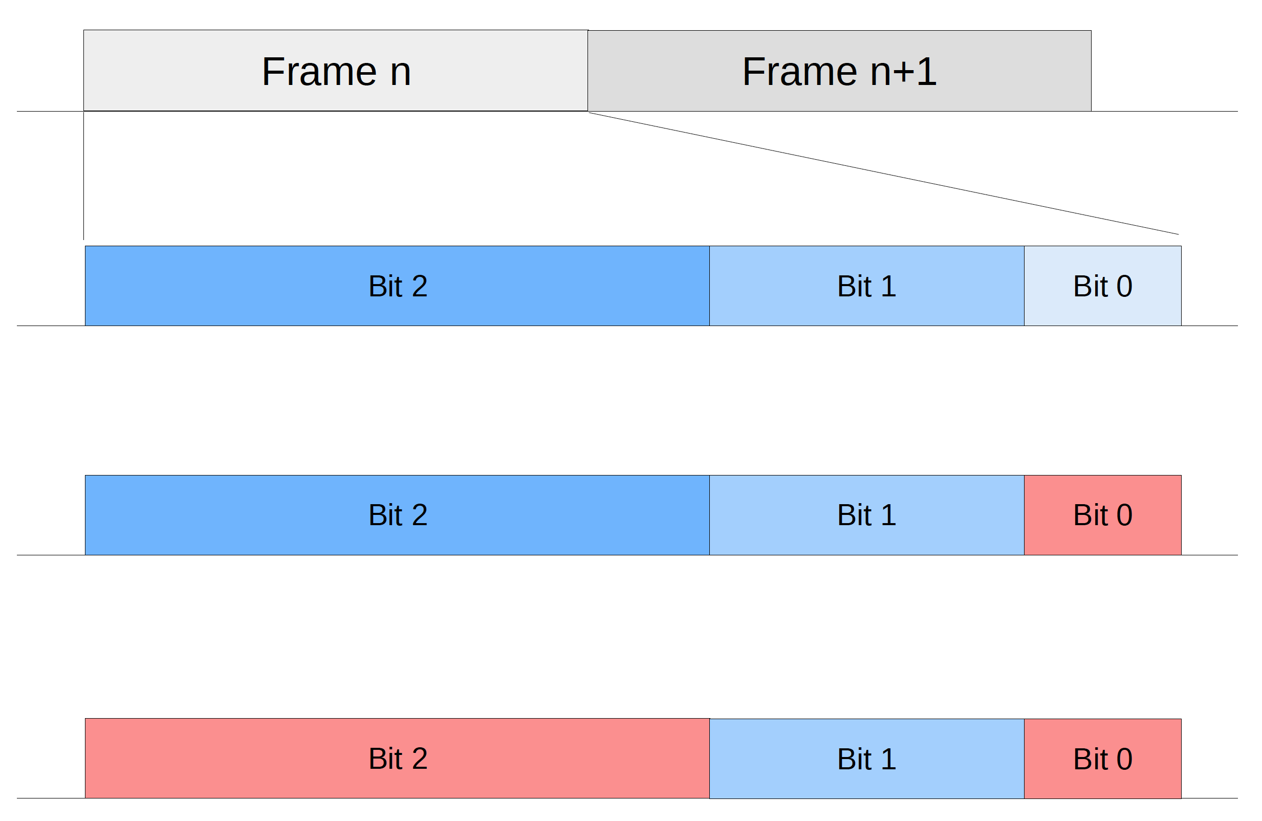
A popular technique to optimize color display on an LED matrix is binary code modulation (BCM). Instead of dividing a frame into (2N – 1) slots of equal duration, we divide it into N intervals of geometrically increasing durations. Let’s label these intervals from 0 to (N – 1). We can associate interval i to bit i of the intensity value (N-bit encoded) and set the duration of interval i to (2i x T) where T is a constant representing the duration of the shortest interval (i.e. interval 0). Below is an example of using BCM for a single LED with N = 3. You may compare it with the PWM example shown above, noting that T is equivalent to a slot duration in the PWM example.
Now it’s time to put everything together. We have just seen how to use BCM to efficiently control the intensity of a single LED. To drive the entire LED matrix, however, we need to continuously scan through all the rows of the panel as illustrated at the top of this episode. Combining row scanning and BCM, we simply repeat for all the rows when clocking out the color data in each BCM interval, as illustrated in the overall timing diagram below.